
I. Architecture Diagrams
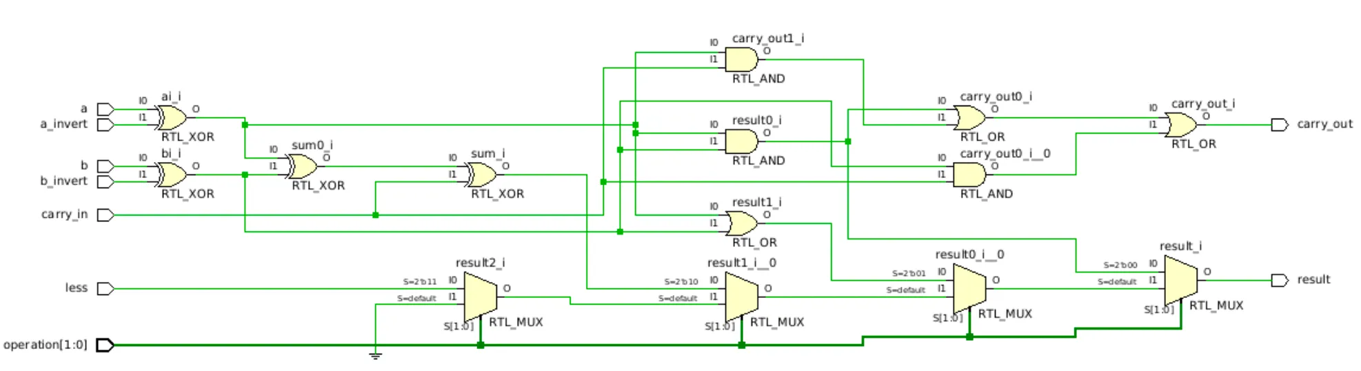
Below is the architecture diagram of the 1-bit ALU (LSB):
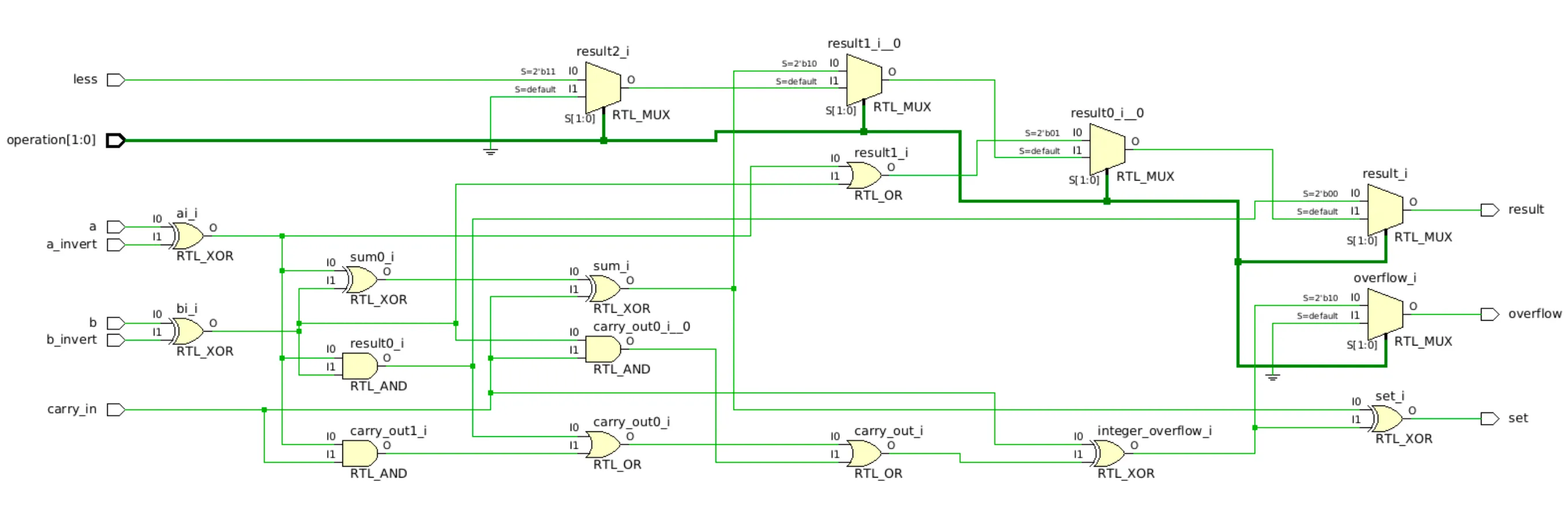
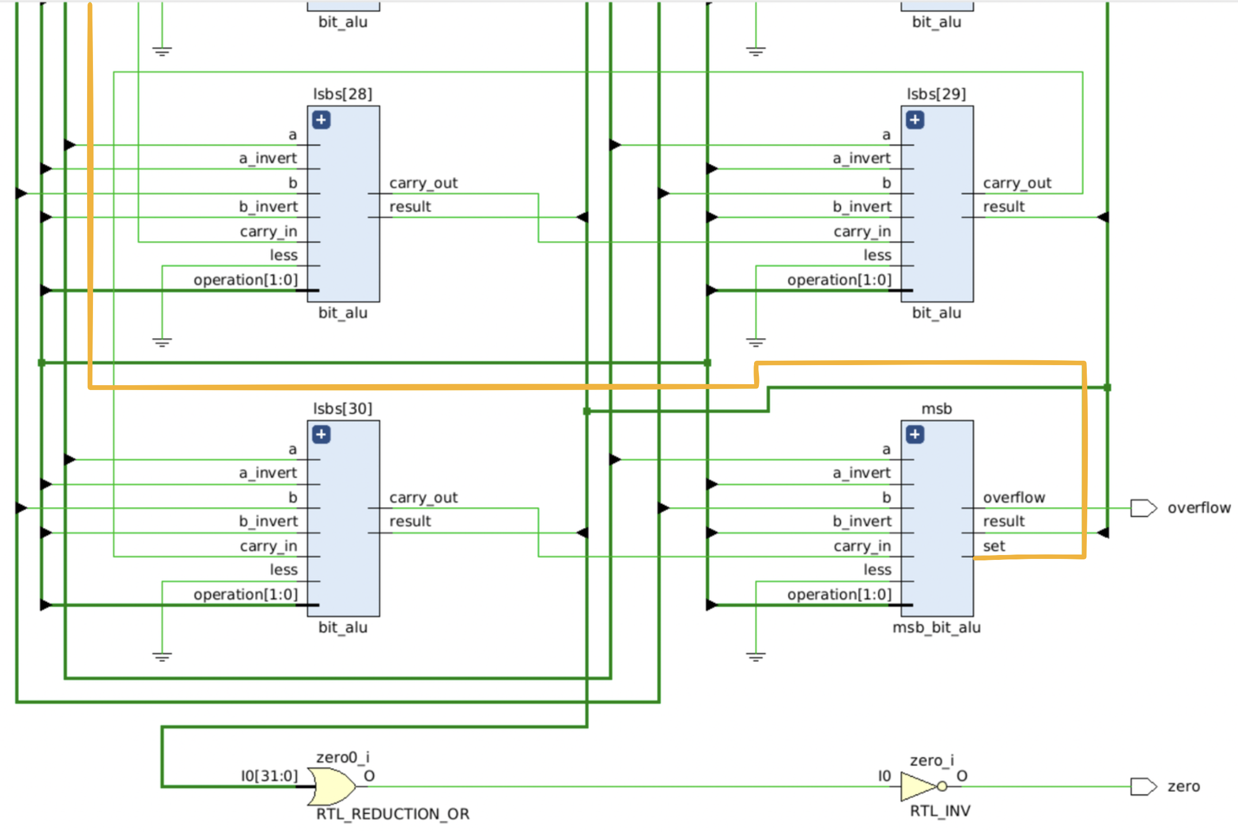
Below is the architecture diagram of the 1-bit ALU (MSB):
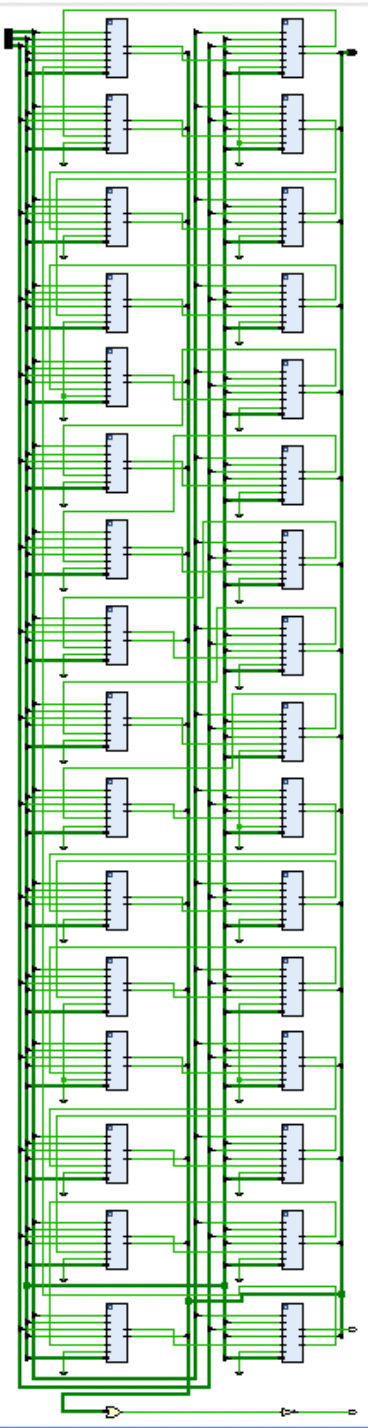
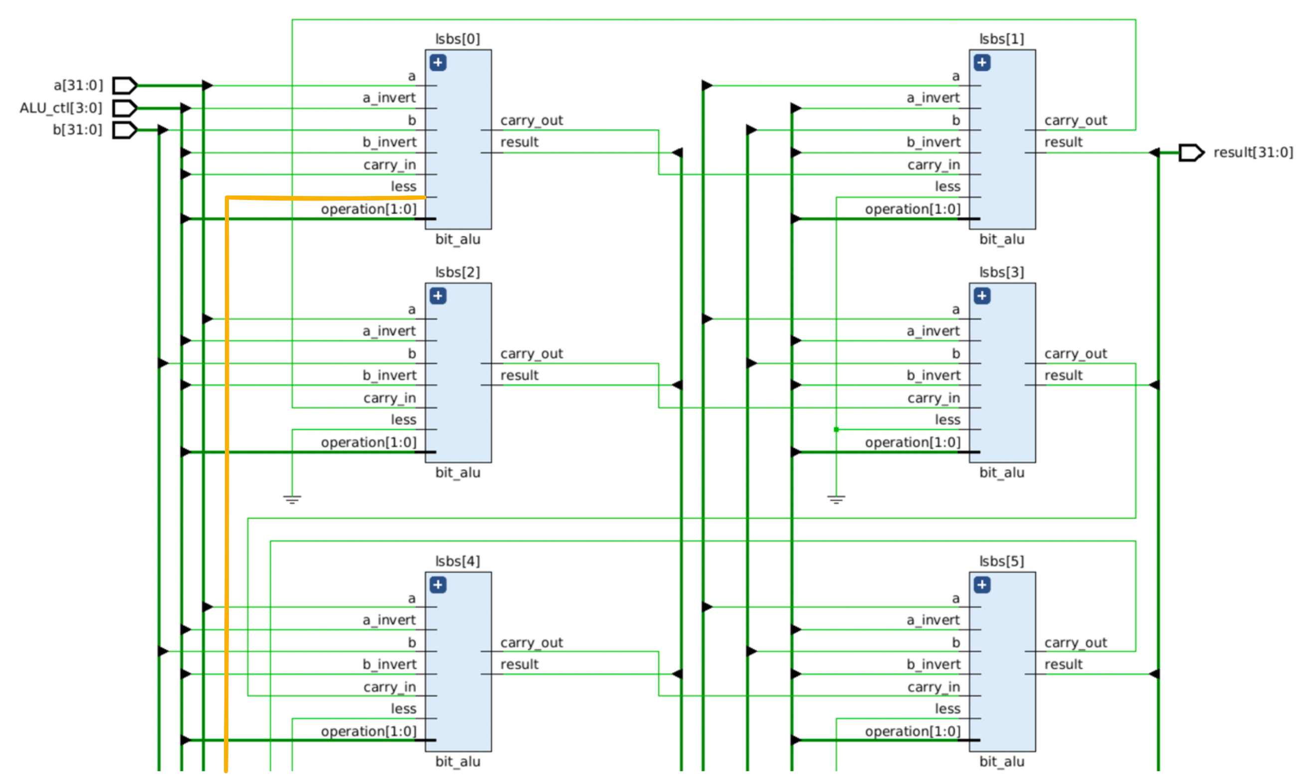
Below is the architecture diagram of the 32-bit ALU. The “set” pin of the MSB is wired back to the “less” pin of the LSB, indicating the result of slt operation when ALU_ctl is 0111.
II. Questions
How overflow is calculated?
The overflow only happens when adding two positive numbers or adding two negative numbers (equivalently, subtracting a positive number from a negative number or subtracting a negative number from a positive number). WLOG, we only need to consider the cases of addition.
Suppose we are adding two -bit numbers and , where and have the same sign. Suppose is the carry-in of the MSB, and is the carry-out of the MSB.
If and are both positive:
- is overflow occurs, is
- is no overflow, is
If and are both negative:
- is no overflow, is
- is overflow occurs, is
The detection of overflow for signed integer addition/subtraction can be elegantly done by xoring the carry-in and the carry-out of the MSB:
If the result is , then overflow occurs.
According to the spec, the overflow detection is only activated when the operation is ADD or SUB, so additional logic is needed to handle this case.
wire integer_overflow = carry_in ^ carry_out;
assign overflow = (operation == 2'b10 ? integer_overflow : 1'b0);
Explain why ALU control signal of SUB is 0110 and NOR is 1100?
Subtraction is equivalent to adding the 2’s complement of the second operand:
Hence, it’s natural to set the control signal of SUB to 0110, which is the same as ADD but with the 3rd bit inverted (ALU_ctl[2] = 1). Furthermore, we need to set the carry_in of LSB to 1 to handle the +1 in the 2’s complement.
assign carry_in = {carry_out, ALU_ctl[2]};Similarly for the NOR operation, according to De Morgan’s law:
which means we can first invert both operands, then perform AND operation. This is equivalent to setting the control signal of NOR to 1100.
If you assign different signal to these operation, what problems you may encountered?
The circuit will be more complicated and it will take more time (require extra logic gates) to decode the control signals.
True or false: Because the register file is both read and written on the same clock cycle, any MIPS datapath using edge-triggered writes must have more than one copy of the register file. Explain your answer.
False.
A single register file is sufficient because it is designed with independent read and write ports. The processor typically employs a split-cycle design, where writes are executed in the first half of the clock cycle (e.g., triggered by the falling edge) and reads are resolved in the second half. This ensures no structural hazards or data conflicts occur, eliminating the need for multiple copies of the register file.
III. Experimental Result of ALU
Show the waveform screen shot of the testbench tb_alu.0.txt result.
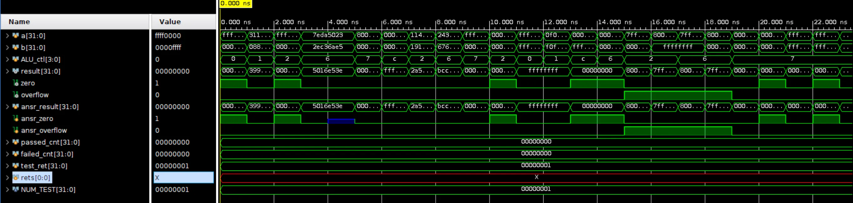
What other cases you’ve tested? Why you choose them?
// Random
0x11451400 0x19191800 ADD 0x2a5e2c00 0 0
0x24342434 0x67676767 SUB 0xbcccbccd 0 0
        -7          6 SLT          1 0 0
// Logical Operations and Zero Flag
0x00000000 0x00000000 ADD 0x00000000 1 0
0xffffffff 0xffffffff AND 0xffffffff 0 0
0x0f0f0f0f 0xf0f0f0f0 OR 0xffffffff 0 0
0x00000000 0xffffffff NOR 0x00000000 1 0
10 10 SUB 0 1 0// Overflow
0x7fffffff 0x00000001 ADD 0x80000000 0 1
0x80000000 -1 ADD 0x7fffffff 0 1
0x7fffffff -1 SUB 0x80000000 0 1
0x80000000 1 SUB 0x7fffffff 0 1// SLT
10 20 SLT 1 0 0
20 10 SLT 0 1 0
-5 -2 SLT 1 0 0
-2 -5 SLT 0 1 0// SLT with Overflow (Exercise C.24)
0x80000000 0x7fffffff SLT 1 0 0
0x7fffffff 0x80000000 SLT 0 1 0IV. Problems Encountered & Solution
List some important problems you’ve met during this lab and their solution.
Vivado does not support MacOS.
I found this GitHub repo:
It provides a way to run Vivado inside a Docker container (distro: Ubuntu 22.04). After 1 hour of installation and setup, I successfully ran Vivado on my MacBook.
The trade-off is that the performance is slower than running Vivado directly on a Linux system. Hence, for the development, I used Icarus Verilog for compilation and running the testbench.
iverilog -g2012 -o lab1_alu.out tb_alu.sv src/alu.v src/bit_alu.v src/msb_bit_alu.v
./lab1_alu.out
V. Feedback
Lab 好玩!